
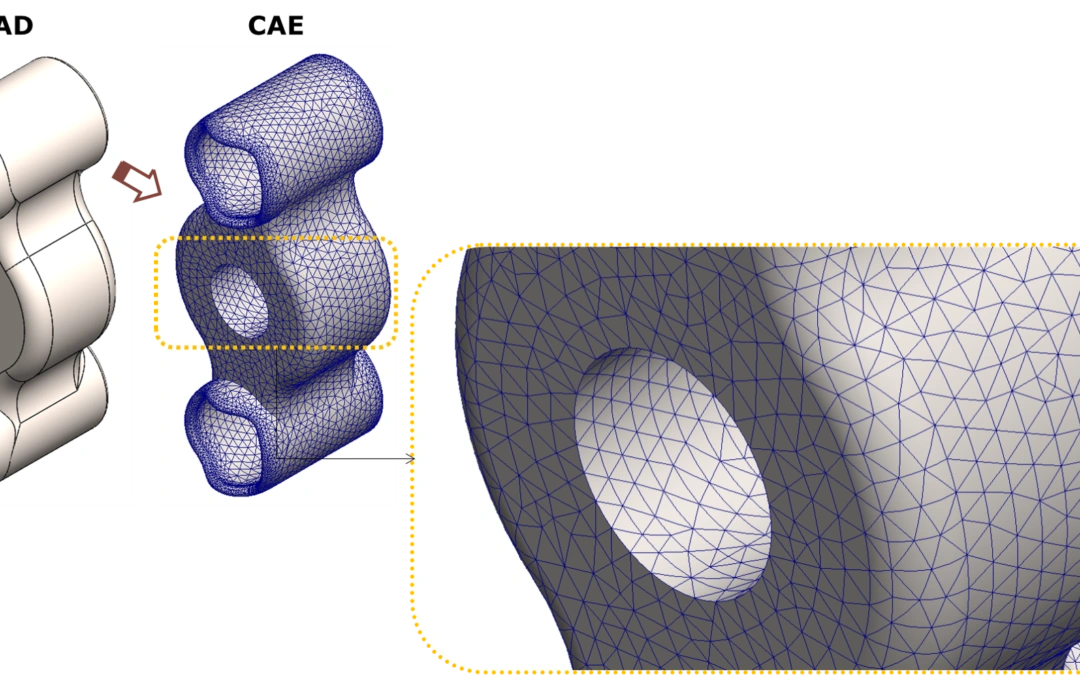
The mesh is one of the foundations of a finite element model. Before a solver can estimate how a component behaves, its geometry must be represented by a set of elements. Choosing those elements is an engineering decision: it affects which behavior the model can capture, how much computational effort is required and how useful the results will be.
This article explains the main ideas behind meshing in CAE simulation and the differences between solid, shell and beam elements. It is adapted from areaFEA’s original article by Abed, published on April 30, 2024.
What is meshing in CAE simulation?
Meshing is the process of discretizing a geometry into finite elements. Instead of working directly with the complete continuous domain, the finite element method uses a collection of smaller regions in which the unknown fields are approximated. The solver assembles their equations into a system representing the model.
Elements connect through nodes. In a compatible mesh, shared nodes connect neighboring elements and their degrees of freedom. For a structural problem, these degrees of freedom describe quantities such as displacement and, depending on the formulation, rotation.
The mesh is only one part of the analysis. Material properties, loads, boundary conditions and connections must also represent the intended physical problem. Boundary conditions apply to the model; they are not separate conditions that must be assigned to every element to make its solution “finite.”
Solid elements: representing the volume
Solid elements discretize the volume of a component. Common shapes include tetrahedra, hexahedra, wedges and pyramids. They are useful when the three-dimensional behavior or local geometry matters, such as near a connection, a contact region or a thick component.
For example, the area around a hole in a bracket may require a volume model to investigate local behavior. The mesh must still represent that region with sufficient resolution and suitable element quality. Using solids does not automatically make a model accurate.
Linear and quadratic tetrahedra
A conventional linear tetrahedron has four corner nodes. A quadratic tetrahedron has ten nodes, including six midside nodes. The higher-order interpolation can represent variations within the element more flexibly, but suitability depends on the problem, formulation and mesh quality.
Element order is therefore a choice to assess, not a substitute for checking the model. A coarse or distorted mesh can remain inadequate even when higher-order elements are used.
Shell elements: modeling thin-walled parts
Shell elements represent a thin-walled component through a reference surface, with thickness and material information assigned to that surface. Although the displayed mesh may look flat, the thickness contributes to the element’s structural response.
This approach can be useful for sheet-metal components or other structures where thickness is small relative to the dimensions along the surface. Compared with resolving the same part using a volume mesh, an appropriate shell model can reduce computational effort.
What must a shell model retain?
The reference surface, thickness, orientation and connections must remain consistent with the physical part. Simplification should preserve the response being studied. If a local three-dimensional effect is important, a shell representation may not provide the information needed there.
Shell meshes can use triangular or quadrilateral elements. A conventional linear triangle has three corner nodes, while a quadratic triangle has six nodes, including midside nodes. As with solids, mesh density and element quality still require attention.
Beam elements: simplifying structural members
Beam elements represent members through lines and assigned cross-section properties. The geometric section, material and local orientation describe how each member responds to loads. They are often useful for frames built from slender structural profiles.
Consider a frame made from square hollow sections. A beam model can represent its members without meshing every wall of each profile. This can make it easier to explore the overall load path, stiffness and deformation of the frame.
Connections and local detail
The way members connect is important. A rigid connection and a released connection do not represent the same behavior. Sharing a node alone does not establish that the joint matches the real assembly; its degrees of freedom and connection assumptions must be reviewed.
A beam model is not intended to resolve detailed stresses around a bolt hole or a weld toe. When those local effects matter, a shell or solid model of the relevant region may be more appropriate.
How to choose a mesh for your engineering question
Start with the result you need. Global frame behavior may suit beam elements; thin-walled behavior may suit shells; local three-dimensional effects may require solids. Some models combine element families, but their interfaces must transfer the intended forces and motions consistently.
Then review mesh quality and refine where necessary. Compare the quantity of interest across successive meshes, rather than assuming that more elements always produce a trustworthy answer. Keep the physical assumptions consistent while checking the effect of discretization.
A useful model balances detail and computational effort while remaining suitable for its purpose. To revisit the wider analysis process, read what finite element analysis is and what it is used for.