In this post, we will delve into one of the fundamental aspects of the Finite Element Method, which is the Mesh in CAE Simulations. Selecting the appropriate type of elements is crucial for accurate simulation results.
Let’s go for it,
MESH IN CAE SIMULATION
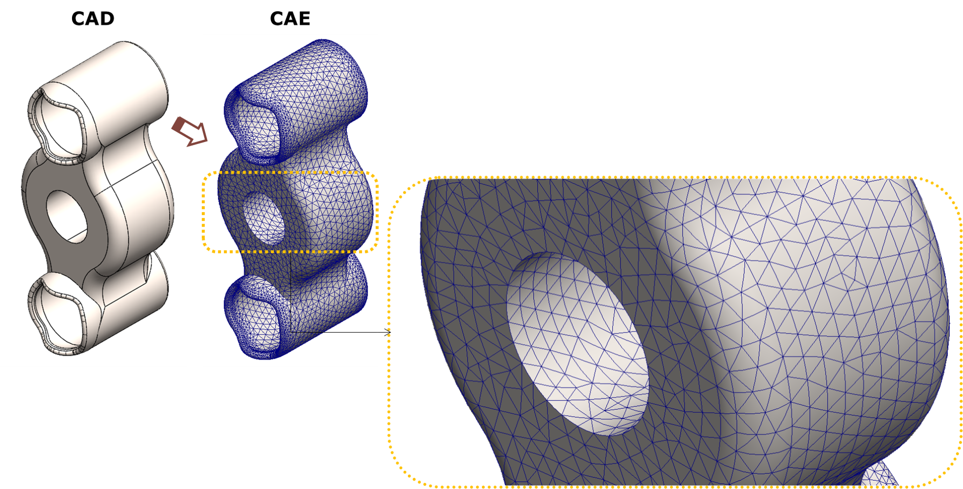
As we saw in this post about “What is the Finite Element Method?“, the FEM breaks down a CAD Model into small, more manageable parts called finite elements. These elements are interconnected at specific points, forming a mesh that represents the entire system.
Therefore, we define the process of meshing as the way which involves discretizing the CAD geometry into polygonal (finite) elements.
This is one of the most crucial steps when preparing a Finite Element Model due to it will depend of how accurate our simulation will be.
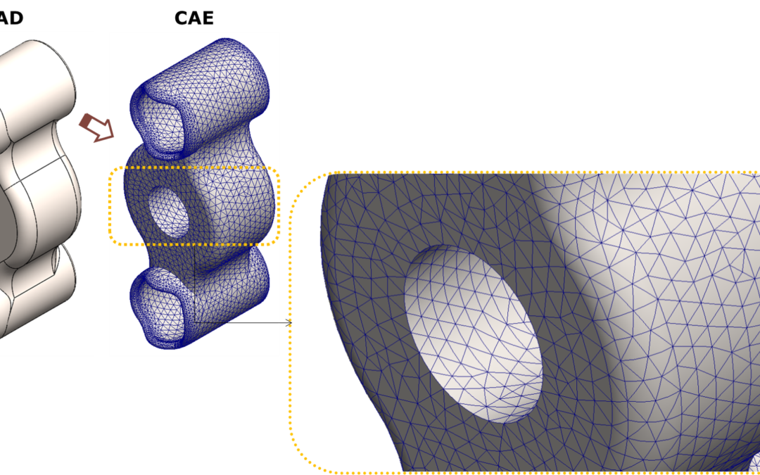
In the picture below, it can be seen the process of discretizing the CAD geometry to obtain the mesh for the CAE Model.

The elements shown in the picture above will be linked by common points called nodes. These nodes will allow continuity along all the Finite Element Model. The following example shows this concept in more detail:

Going into more technical and deeper words, we can say that, by means of this model divided into smaller elements, we will be able to solve the differential equations that define the physical problem that is being analysed.
This is because in each division we will have a boundary condition that makes these differential equations have a FINITE solution.
Having said that, let’s review which types of elements are the most used:
Normally we are going to simulate 3D Models. However, we will have the possibility to simplify these models in order to avoid long simulations and save time. This means that, depending of the Model, we can use different types of elements: 3D, 2D or 1D.
Let’s go into more details to understand this paragraph:
SOLID ELEMENTS
The 3D elements are formed by solids elements. These are able to fill the volume of the geometry with polygonal shapes such as tetrahedrons, pentahedrons or pyramids.
Using solid elements would achieve a high accuracy when reproducing 3D CAD geometry into our CAE Simulation.
In addition, Finite Element software usually offers the possibility of using high precision 3D elements. These elements contain intermediate nodes between their edges for a better accuracy.
Considering a tetrahedron shape, we could differentiate between linear elements (4 nodes) and quadratic elements (10 nodes). Example below:

SHELL ELEMENTS
We can say that solid elements give us a high precision to prepare our CAE Simulation Model.
However, there will be situations in which it will not be necessary to use this type of 3D elements. In those cases, we can simplify the mesh with 2D or even 1D elements.
This will significantly reduce the computational cost when calculating our CAE Simulation Model.
These 2D elements or Shell elements will reproduce the 3D geometry as a surface without thickness so that the thickness is defined for that surface.
The thickness of each part will be defined and considered by the program when solving our model even if it looks as a flat surface.
The following example shows how a 3D beam has been simplified to 2D and, as a result, the mesh elements that make it up:

The only thing we have to do is to define the thickness of these shell elements so that the CAE Software takes it into account when solving the simulation.
As for the solid elements, in the surface elements we can also find high precision elements. So, we will differenciate between linear elements and quadratic elements which will have intermediate nodes on their edges.
Considering a triangle that forms the mesh of shell elements, we would have 3 nodes for linear elements and 6 nodes for quadratic elements.

Despite losing the high accuracy that solid elements offer us, we see that, with shell elements, we could have a very accurate solution as well.
BEAM ELEMENTS
If we continue with the simplification of a Finite Element Model, we find the possibility of using 1D elements. Commonly called “Beam Elements”.
As the name implies, these elements are widely used for structural calculations where most of the components are beams. Then, each beam will be defined by a cross section which represents the replaced profile. So, the beam element will have the mechanical properties related to that profile section.
At the end, the solver will have it into account this data when running the simulation in order to obtain the correct behaviour of the beam element and, of course, the entire structure.
Below, you can see an example to understand it better. It is a simple structure where the mesh is formed by beam elements replacing the structural square profiles.

We can see that, at the extremes of each beam, there are spheres called joints which connect the elements of different beams. By means of these joints, we can define the boundary conditions of the CAE Simulation Model. We will see it below at the Real Example.
Using beam elements in our mesh when performing a CAE Simulation of a structure will provide us results very fast. So, we will be able to analyse the results more efficiently.
In case we have a more complex area in our model that we want to study in detail, we can always go back to the 2D and 3D elements to study that concrete area.
Now, I will leave the theory aside and go to the Real case of this post so you will experiment how to make a CAE calculation with beam elements.
Let’s go for it!!

